Bosch 3S Charger Reverse Engineering
Teardown & Reverse Engineering
Reverse engineering of a Dremel 12 V battery charger.
The chargers specifications according to the manual:
Voltage range: 1-3 cells, 3,6 - 12 V
Charging current: max. 1500 mAh
Reverse Engineering
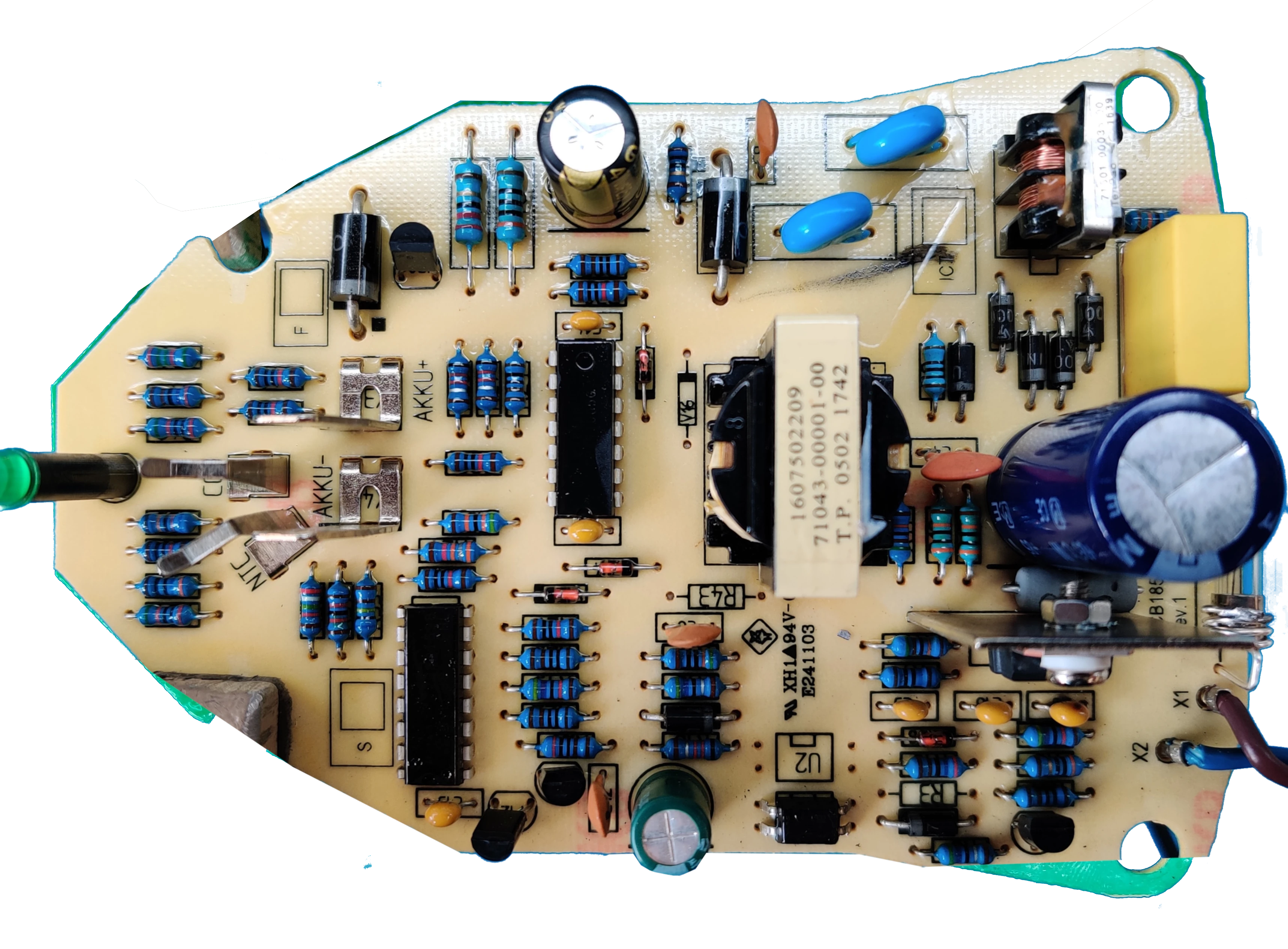
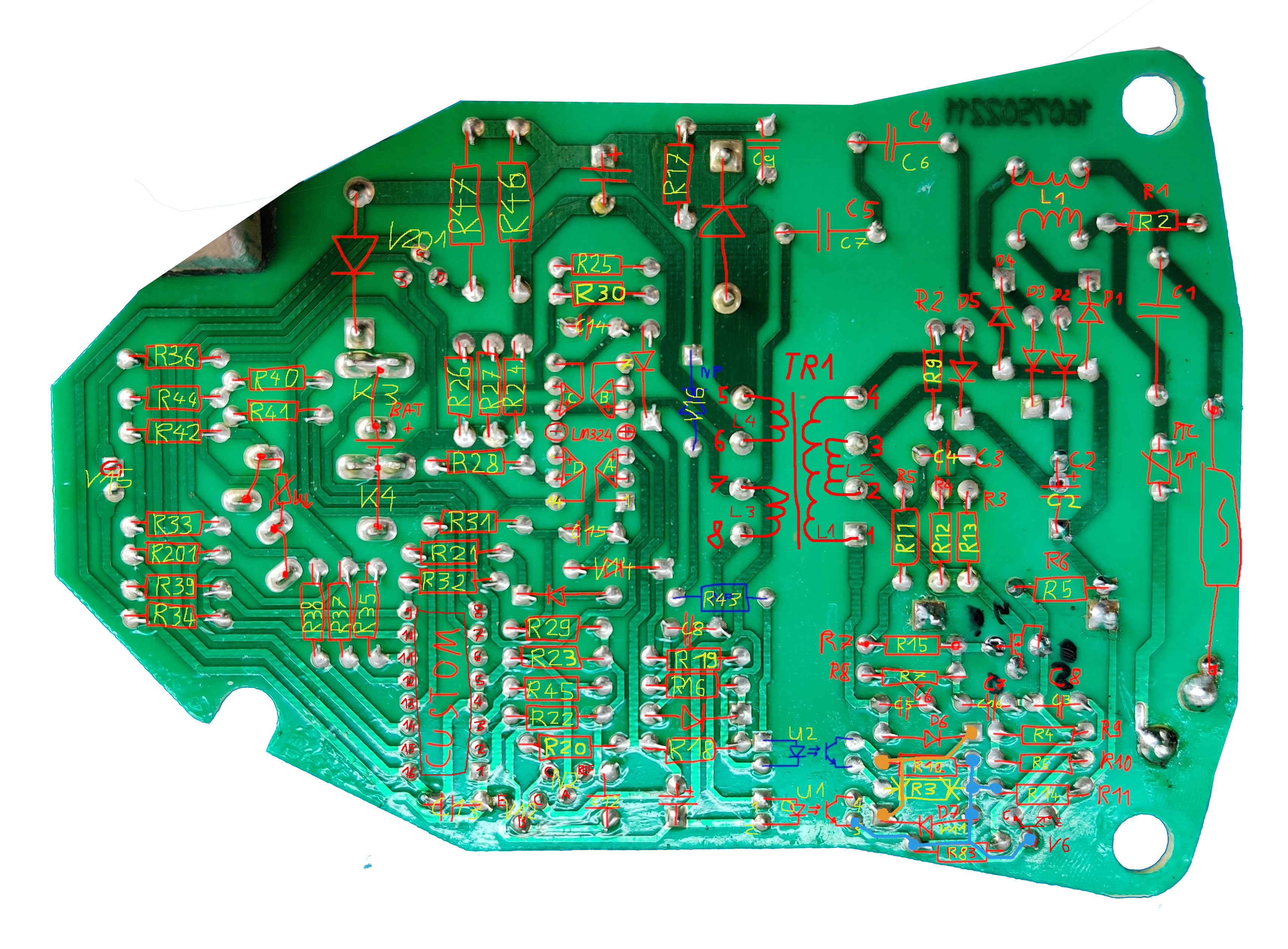
Two pictures were taken to trace the connections on the pcb. Since this is a simple one sided pcb this was fairly easy. The pcb has the markings: PCB1857V1


Proposed Working Principle
The following is my own theory and is only supported by a couple measurements. The charger circuit is visibly divided into two sections: The primary, high voltage side of the smps and the secondary controller side. The secondary side has two supplies VDD and VCC. VCC powers the micro controller (uC, a custom jobby by ST-Microelectronics) and other ICs. VDD is the battery voltage plus one forward voltage drop. When no battery is connected the VDD idles at 1,6 V and the VCC at 13 V.
When a battery is detected by the micro controller the supply voltage is set to induce the desired charging current or constant voltage. The supply voltage is increased via the feedback path over the optocoupler U1. By increasing the photo-transistors c/e-resistance the Vbe of V1 is decreased which again increases Vgs of V5, letting current flow for a longer portion of a period in the switching cycle.
Battery
It is an open secret that Bosch and Dremel (Dremel being a division in the Robert Bosch Tool Corporation since 1993) batteries are compatible except for the bottom plastic shell with the retainment clips. I would bet that they are probably even manufactured in the same factory.
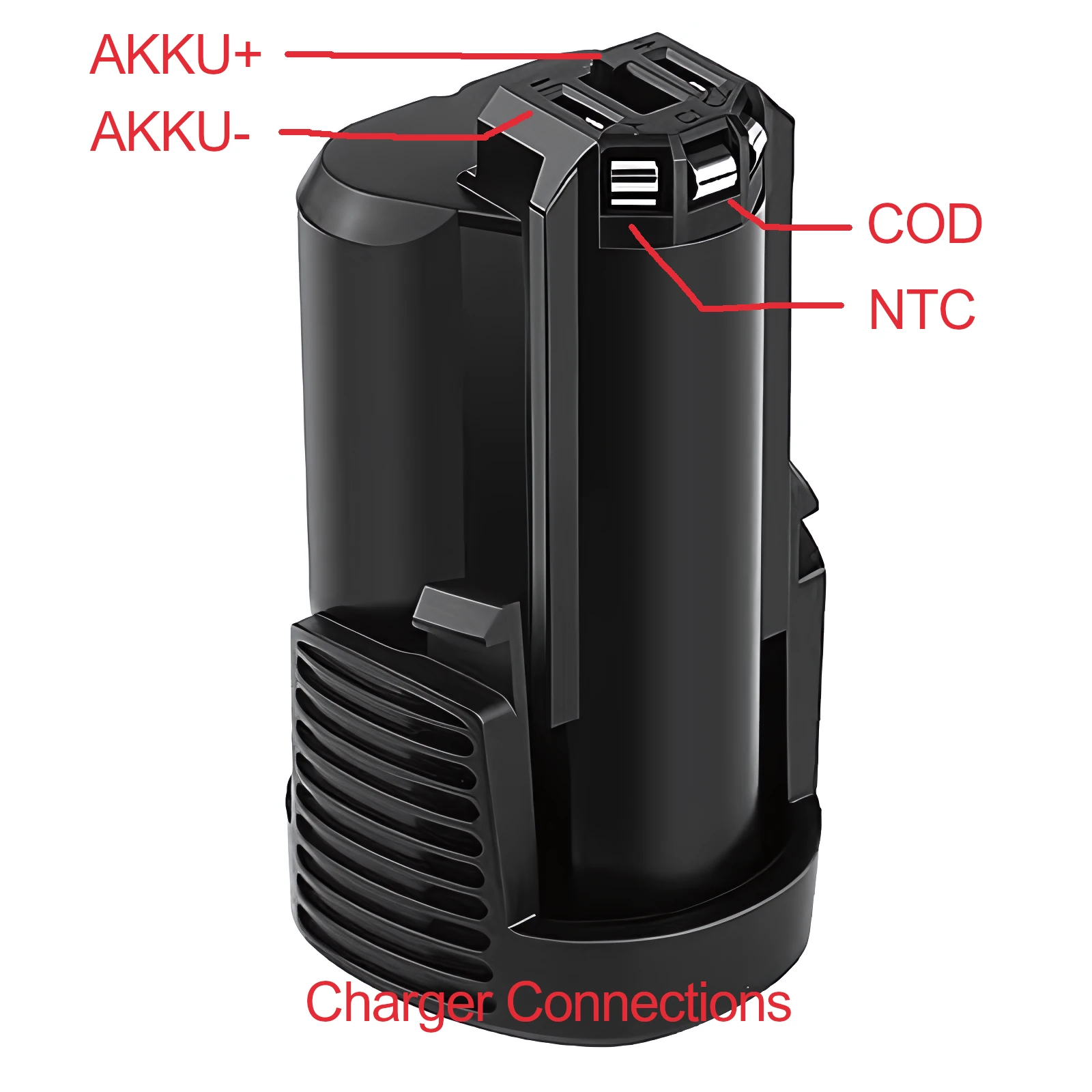
The battery has five contacts, two for providing power, one for the ntc and two additional contacts labeled “C1” and “C2”. It would be reasonable to suspect that these two expose the anode of the first and second 18650 cells inside but only C1 and the ntc are actually connected to the charger. So there is definetly no balance charging happening.

The kicker however is that inside the Bosch GSR BAT411 the both C1 and C2 are not actually connected to the batteries. I have confirmed myself that this is also the case for the Dremel battery.
From what I could gather by probing the battery terminals and looking at some pictures online the battery is connected like this internally. I would suspect that the charging current is advertised this way.
Why could this be a problem?
The connections to the individual battery cells are required for balance charging. Due to manufacturing variations the internal resistance R1, R2 of two cells can vary. When the battery is discharged a current I is flowing through all cells equally due to Kirchhoff’s current law. This causes the voltages of the individual cells to decrease according to
\[\begin{align*} U_1 = R_1 \cdot I \\ U_2 = R_2 \cdot I \end{align*}\]Resulting in a voltage difference of
\[\begin{align*} \Delta U = U_1 - U_2 \end{align*}\]When the battery gets charged again this difference would get annihilated if the resistances were constant, but they are not. Over many discharge/charging cycles the voltage difference can grow to be substantial which could cause the battery to fail because:
a) One cell get under discharged, or
b) the other cell gets overcharged.