Dyson DC34 AnimalPro Repair
This one doesn't brick itself if you leave it unattended! Great job Mr. Dyson!
My friend Idi saved this one from the trashcan so I offered to repair it for her.
Symptoms & Defects
- The filter retainment clip on top is broken.
- The vacuum works as intended but shuts off after a short time. When pressing the trigger again the vacuum again works for a short duration. The on-time decreases after consecutive trigger pulls.
Issue 1
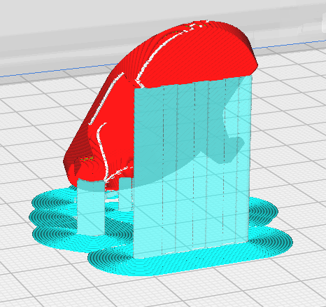
The broken clip is scanned with an EinScan 3D scanner. This scan is used as a reference in cad to model a replacement part. The part is printed on a fdm 3D-printer in PETG filament matching the original colour.
Slicer settings
The orientation of te part during printing should maximize the strength of the pins holding the clip in place. To improve the appearance of the part special care should be taken by placing the seams on the underside of the finished part. For this cura offers special settings for seam placement, the “smart hiding” option was used in combination with manual seem orientation. The seam position is marked as white dots on the sliced part in the picture below. To download this model check out my GrabCAD page.

Issue 2
Working theory: The battery cells are old and as a consequence of that their voltage drops fast when discharging until it riggers the undervoltage protection of the bms (battery management system). Once the output is shut off the cell voltage recovers and the protection mechanism disengages only to trigger again, but quicker the next time.
Battery disassembly
The battery shell is hold together with clips in the same location as the other dyson batteries.
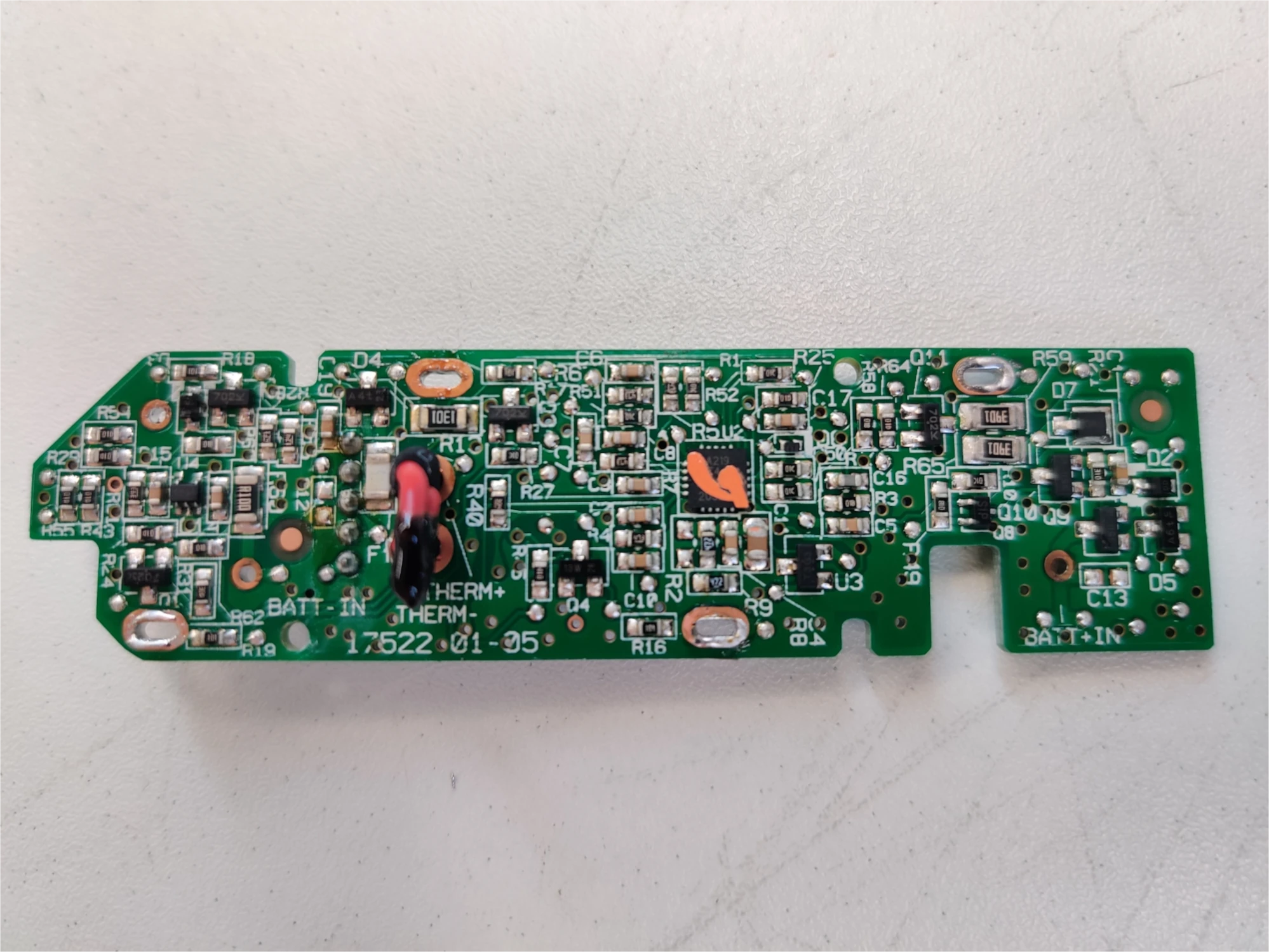
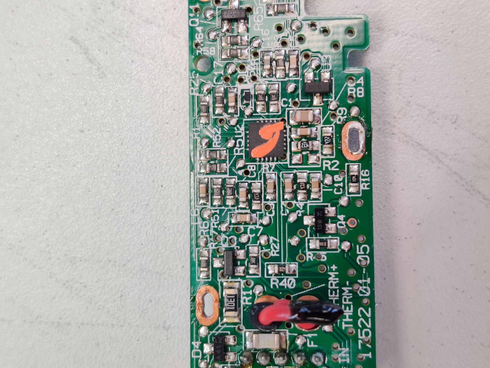
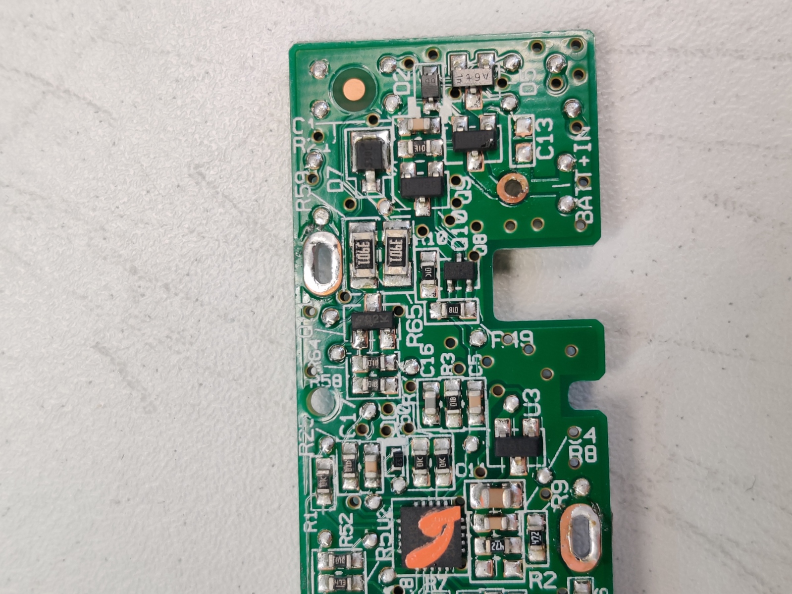
The BMS
The best feature of this battery is that it doesn’t deactivate itself like the V6 battery bms does when the cell voltages get unbalanced, which can happen very easily if you leave the vacuum lying around for a couple of months!
Anyways, the most negative cell voltage is connected to P4 and the most positive cell voltage is connected to P2. I was not able to identify the microcontroller on the front.


Cells
The battery is comprised of 6 Sony US18650VT cells with the following stats:
| Rated capacity | 1300 mAh |
| Nominal voltage | 3.6 V |
| Charging | 4.2 V max. |
| Discharging | 2.75 V |
The cells where removed from the battery back and charged/discharged to measure their remaining capacity, which turned out to just 700 mAh @ 1 A/ 28 mAh @ 8 A discharging current. Obviously this is not sufficient and confirms the thesis. The cells were replaced with OEM cells with a capacity pof 3000 mAh from a salvaged e-bike battery.

Tests
To confirm that the new batteries could provide the required current the new battery pack was investigated with a current probe attached to an oscilloscope. The first screenshot shows the current draw (100 mV/A) of the vacuum in normal mode, it first ramps up to 6,5 A and then drops to a constant current draw of 5 A. In MAX mode the ramp can be observed at the start but then the current increases in two steps, first to 8,5 A and finally to 11,2 A. At first I tried different cells (the light blue one displayed in the thumbnail) which could not handle the full 11,2 A, as a result the vacuum managed to draw the 8,5 A but shut down shortly after the second, probably because the voltage drop tripped the undervoltage protection, but I cannot confirm.

